

New Strain Gauge or Load Cell Transmitters
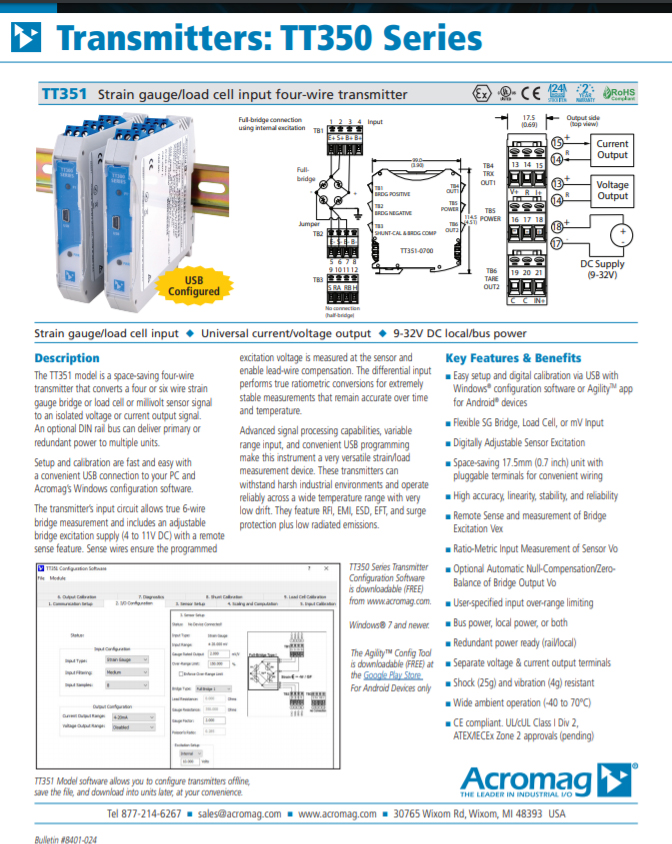
New Strain Gauge or Load Cell Transmitters Simplify Bridge Sensor Measurements with Easy Software Configuration and Advanced Functions
Software provides powerful signal conditioning capabilities for precise conversion of bridge inputs to process current or voltage control signals.
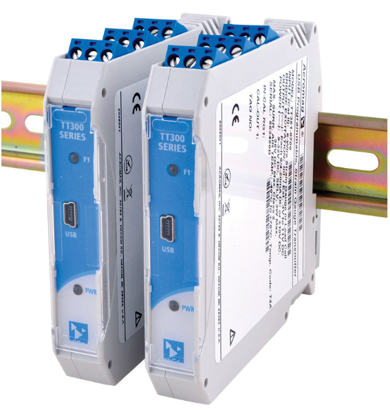
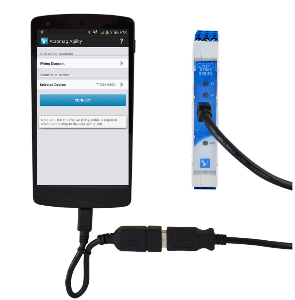
Acromag’s new TT351 load cell or strain gauge signal conditioners use software to quickly select from a wide variety of sensor measurement options. A USB port simplifies setup on a Windows PC or Android mobile device with Acromag’s AgilityTM app.
Software menus help users set the sensor type, bridge configuration, excitation source, filtering level, and input/output ranges. Advanced capabilities let users fine tune scaling of I/O signals, adjust excitation levels, and calibrate the bridge. Universal output supports six ranges including 4-20mA, 0-10V and ±10V. Flexible power accepts a 9-32V DC supply at the terminals and a rail power bus option can supply multiple units from a single connection or establish redundant power. The narrow 17.5mm housing mounts easily on a DIN rail. Hazardous location approvals, high noise immunity, and a -40 to 70°C operating range make these transmitters ideal for use in harsh environments.
Performance Specifications
IMPORTANT: To prevent damage or errors from grounded PCs and surges, Acromag strongly recommends use of their USB-ISOLATOR when configuring a TT350 Series transmitter.
USB Interface
USB Connector
Type: USB Mini-B type socket, 5-pin.
Data rate: 12Mbps. USB v1.1 and 2.0 compatible.
Maximum cable length: 5.0 meters.
USB Transient Protection
Transient voltage suppression on power and data lines.
Driver
Not required. Uses Windows HID drivers.
General Input
Analog to Digital Converter (ADC)
24-bit S-D A/D converter.
Resolution
Varies from 13.5 to 20.5 bits per filter and gain selection.
Input Reference Test Conditions
Strain gauge/mV; Excitation = 10V; Rated Output = 1mV/V; Range = ±10mV; Ambient Temperature = 25°C; Power Supply = 24V DC.
Accuracy (overall input to output)
Better than ±0.1% of span, typical. This value does not include sensor errors.
Ambient Temperature Effect
Better than 0.008% of input span per °C (±80ppm/°C).
Noise Rejection
Normal mode @ 60Hz: -19dB (no filter), -34dB (low filter), >80dB (med/high filter).
Common mode @ 60Hz: -136dB, typical with 100 ohm input unbalance.
Input Overvoltage Protection
Bipolar Transient Voltage Suppressors (TVS).
Bridge Input
Input Types
Select from basic load cell, two quarter-bridge options, two half-bridge options, three full-bridge options, or millivolts.
Input Span/Range
Bipolar input range is determined from the ± product of the gauge’s rated output and the nominal excitation selection (2mV/V x 10V = ±20mV range).
Input Over-range
The actual input range is up to (user-specified) ±150% of the range obtained via the ± product of the gauge’s rated output and the nominal excitation applied.
Input Sensitivity
Accepts gauge rated outputs up to 1mV/V to 10mV/V. The range of your input signal is the ± product of the excitation voltage and your gauge’s rated output.
Input Impedance
±IN at 15M ohms, ±SEN at 73.2K ohms, typical.
Input Lead Resistance
Module has sufficient overdrive to guarantee 10V bridge excitation with 5 ohms/lead and 100mA of internal excitation current. Larger lead resistances may limit the maximum achievable internal bridge excitation.
Input Bridge Excitation (Internal)
Adjustable from 4V to 11V, 120mA maximum. Internal excitation must be turned OFF before external excitation supply connection.
Input Bridge Excitation (External)
4V to 11V. The internal excitation must be turned OFF for connection to an external excitation supply.
Digital (Trigger) Input
Input Type
“Active High” input, 100ms minimum.
15-30V DC (6.65K ohms).
See connection diagram.
Operation (Tare/Alarm Modes)
The trigger function is set for “Auto-Tare” mode by default.
Output (DC V/mA)
D/A Converter
16-bit.
Current Output
Ranges: 0-20mA, 4-20mA.
Compliance: 10V minimum (525 ohm load).
Voltage Output
Ranges: 0-5V, ±5V, 0-10V, ±10V.
Compliance: 10mA maximum with short circuit protection. 1 ohm output impedance.
Output Response Time to 98% (for step input change)
No filter: 264ms. Medium filter: 472ms.
Low filter: 292ms. High filter: 2547ms.
Environmental
Operating temperature
-40 to 70°C (-40° to 158°F).
Storage temperature
-40 to 85°C (-40 to 185°F).
Relative humidity
5 to 95% non-condensing.
Power Requirement
Supply | Ptot | Current Draw
9V | 3.05W | 339mA Max.
12V | 3.05W | 254mA Max.
15V | 3.05W | 203mA Max.
24V | 3.05W | 127mA Max.
32V | 3.05W | 95mA Max.
Isolation
4-way (input/output/trigger/power). Input/excitation, analog output, trigger, and power circuits are isolated from each other for up to 1500V AC for 60 seconds or 250V AC continuous.
Shock and Vibration Immunity
Vibration: 4g.
Shock: 25g.
Approvals (pending)
CE compliant. UL/cUL listed Class I Division 2 Groups ABCD. ATEX, IECEx certified Zone 2.
II 3 G Ex nA IIC T4 Gc -40°C < Ta < +80°C.
Physical
General
General-purpose enclosure designed for mounting on 35mm “T-type” DIN rail.
Case Material
Self-extinguishing polyamide, UL94 V-0 rated, color light gray. General-purpose NEMA Type 1 enclosure.
I/O Connectors
Removable plug-in terminal blocks rated for 12A/250V; AWG #26-12, stranded or solid copper wire.
Dimensions
17.5 x 114.5 x 99.0 mm (0.7 x 4.51 x 3.90 inches).
Shipping Weight
0.22 kg (0.5 pounds) packed.
Acromag | Who We Are